
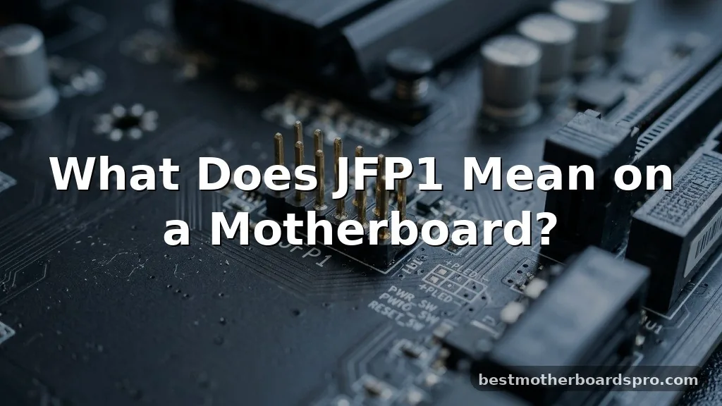
If you are staring at a cluster of tiny pins on your circuit board while trying to figure out what does jfp1 mean on a motherboard, you are definitely not alone. This label is a common point of confusion for anyone building or upgrading a PC, especially if they are working with an MSI board. At its core, JFP1 stands for “Jump Front Panel 1.”
It serves as the primary gateway for connecting your computer case’s essential controls—like your power button, reset switch, and status lights—directly to the logic of your system. Once you understand the pin layout, the process becomes much more manageable.
Every motherboard manufacturer uses a specific shorthand for their headers, and JFP1 is almost exclusively found on boards produced by MSI. While other brands might label these pins as “F_PANEL,” “JFP1” effectively functions as the central nervous system for your case interactions. Without these connections, your computer simply won’t turn on, even if your power supply is plugged in and ready to go.
Learning how to navigate these headers is a vital skill for anyone performing a custom build or simply swapping out a faulty case.
Decoding the JFP1 Connector 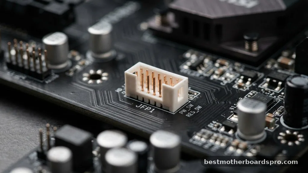
The JFP1 header is a specific collection of pins designed to bridge the gap between your physical computer case and the motherboard. When you press the power button on your chassis, the signal travels through these small wires into the motherboard, which then instructs the power supply to start delivering electricity. Understanding what does jfp1 mean on a motherboard is essentially learning how to bridge that electrical circuit safely.
This header usually consists of nine pins arranged in a rectangular grid. While it looks intimidating, it is a standardized interface. The pins are grouped to accommodate specific functions that provide feedback or control for your PC.
By following the motherboard manual, you can identify exactly which pin controls which function. Most boards have a small diagram printed directly on the PCB, though it can be hard to read without a flashlight.
Key Components of the Front Panel Header
To successfully connect your system, you need to identify the specific wires coming from your case.
Each wire corresponds to a specific pair of pins on the JFP1 header. If you get these wrong, your power button won’t work, or your status lights will stay dark.
* Power Switch (PWR_SW): This is the most critical wire. It allows you to turn the system on and off. It is non-polar, meaning it doesn’t matter which way you plug it into the two designated pins.
* Reset Switch (RESET_SW): This wire triggers a hard reboot of the system.
Like the power switch, it is not sensitive to polarity.
* HDD LED: This light indicates drive activity. Unlike the switches, this is polar; you must ensure the positive and negative sides match the motherboard’s requirements.
* Power LED: This light signals that the system is receiving power. This is also polar and usually requires careful orientation to illuminate correctly.
Understanding Polarity and Pin Layout
One of the most frequent mistakes during motherboard installation is ignoring polarity.
While switches are forgiving, LEDs are diodes, meaning they only allow electricity to flow in one direction. If you plug your HDD LED or Power LED in backward, the light simply won’t turn on. You won’t damage the motherboard, but you will have to reach back in and flip the connector.
The motherboard manual is your best friend here. It will feature a detailed pin configuration diagram that maps every pin to its specific role.
If you have lost the physical manual, you can find the digital version on the manufacturer’s website by searching for your specific model number. The schematic will show you exactly which pin is positive and which is negative.
| Connector Type | Polarity Sensitive | Function |
|---|---|---|
| Power Switch | No | Toggles system power |
| Reset Switch | No | Reboots the hardware |
| HDD LED | Yes | Indicates disk read/write |
| Power LED | Yes | Indicates system power status |
Connecting Front Panel Cables
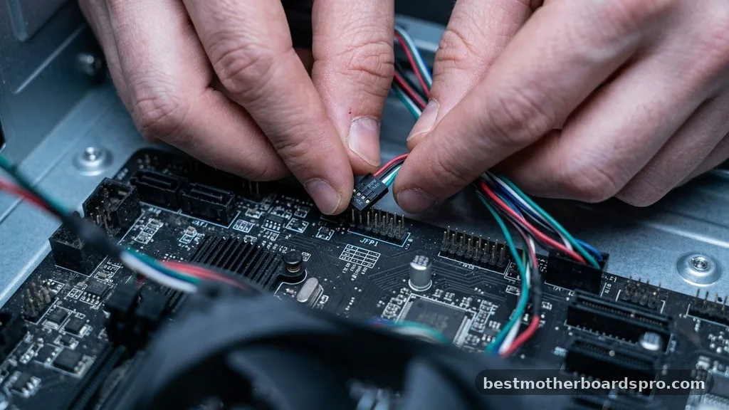
Installing these cables requires a steady hand. Because the pins are small and located at the bottom edge of the board, it is often easier to connect them before you install your graphics card or other bulky components. If you are working in a tight case, a pair of long-nose tweezers can help you guide the connectors onto the pins.
Many modern MSI motherboards include a small plastic block called a “JFP1 module” or “front panel connector block.” You plug your tiny case wires into this block first, and then you press the entire block onto the motherboard header at once. This significantly simplifies the process, as it prevents you from having to fiddle with individual wires while reaching into dark corners of your chassis.
Troubleshooting Common Connection Issues
If your system fails to boot after assembly, the JFP1 header is the first place you should look.
It is very easy to accidentally knock a wire loose or plug it onto the wrong pins. If the power button does nothing, double-check that the power switch wires are seated firmly on the correct pins. Sometimes the pins can be slightly bent during shipping or installation, which prevents the connector from making a solid electrical connection.
If your system turns on but the lights don’t work, check the LED polarity. Try flipping the connector 180 degrees. If the light still doesn’t turn on, ensure that the wire hasn’t been damaged during the building process.
Computer case wiring is often quite thin, and it can be pinched or frayed if it is routed too tightly behind the motherboard tray.
Addressing Topical Gaps
A common question that arises is whether JFP1 is universal. While MSI uses the JFP1 label, other manufacturers use different naming conventions for the same system panel connector.
ASUS often uses “F_PANEL,” while Gigabyte might use “F_PANEL” or “PANEL1.” Despite the different names, the functionality remains identical across almost all consumer desktop motherboards.
Another gap in knowledge is the difference between JFP1 and JFP2. While JFP1 is the primary header for the power and reset buttons, JFP2 is often reserved for additional features like a motherboard-mounted speaker or specific LED indicators that are not standard on all cases. You typically do not need to worry about JFP2 for a basic build, as the essential controls are all housed within the JFP1 block.
- Always consult the motherboard manual for the exact pin layout.
- Ensure all case wires are pushed fully onto the pins.
- If a light doesn’t function, reverse the connector polarity.
- Use a flashlight to read the tiny labels printed on the motherboard PCB.
- Double-check that you haven’t plugged the power switch into the reset pins.
Frequently Asked Questions
Is JFP1 the same as the F_PANEL connector on other boards?
Yes, JFP1 is essentially the MSI-specific label for what most other manufacturers call the F_PANEL or system panel header. While the naming convention differs, the purpose of these pins is identical: to connect your case buttons and status lights to the motherboard’s power management system.
Do I need to plug in every wire to the JFP1 header?
You only need to connect the Power Switch to boot your computer. The Reset Switch, HDD LED, and Power LED are optional. If you prefer a minimalist look or your case lacks these features, you can leave them disconnected without affecting the primary operation of your system.
Can I damage my motherboard by plugging these pins in incorrectly?
It is very unlikely to cause permanent damage. If you plug a switch onto the wrong pins, the computer simply won’t respond or may trigger a reset loop.
If you reverse an LED, it just won’t light up. Just power off the system and re-seat the connectors correctly.
What if my case wires are not labeled?
Most modern cases come with clearly labeled connectors, but if yours are unlabeled, consult your case manual. If you no longer have it, look at the wire colors. Usually, white wires represent ground or negative, while colored wires represent positive signals, but checking the manufacturer documentation is safer.
Conclusion
Mastering the connection of your front panel header is a rite of passage for any PC builder. Understanding what does jfp1 mean on a motherboard allows you to take full control of your hardware, ensuring your power and reset switches function exactly as intended. While the tiny pins and cryptic labels might seem intimidating at first, they are designed to follow a logical, standardized pattern that you can easily follow with a little patience and the right documentation.
By taking the time to verify your pin layout and ensuring each wire is seated firmly, you avoid the common pitfalls that lead to a “no-post” scenario. Whether you are building your first rig or troubleshooting an existing machine, this knowledge is a fundamental piece of the puzzle.
If you run into trouble, remember to check your manual and don’t be afraid to double-check your work; most issues are solved by a simple adjustment. Happy building, and enjoy the process of bringing your system to life.